Power steering wiring harnesses are critical electrical components that connect your vehicle's Electronic Power Steering (EPS) control module to the steering rack. The Golf MK7 Power Steering Left Hand Drive Wiring Harness 5Q1971111AA and the 80B971111 Q5 Power Steering Gear Rack Wire Harness are direct OEM-specification replacements designed to restore full steering functionality when original harnesses fail due to wear, corrosion, or physical damage.
Understanding Power Steering Wiring Harness Failures
Power steering harness failures typically manifest as intermittent or complete loss of power assist, dashboard warning lights (EPS fault indicators), or erratic steering behavior. These symptoms occur when internal wire strands break, insulation deteriorates from heat exposure near the engine bay, or connector pins corrode from moisture ingress. The harness routes from the steering column through the bulkhead to the rack assembly, making it vulnerable to flexing stress and environmental damage.
Modern electric power steering systems operate on CAN-bus communication protocols, requiring intact signal wires for proper operation. Even minor wire damage can disrupt communication between the EPS control unit and steering rack motor, triggering fail-safe modes that disable power assistance entirely. Diagnostic trouble codes like C1513 (steering position sensor) or C1538 (rack motor malfunction) often point to harness issues rather than mechanical failures.
VW Golf MK7 Harness Specifications
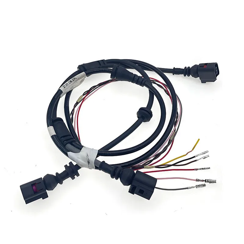
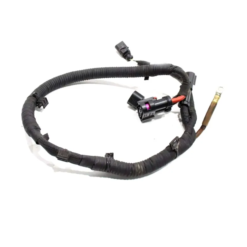
The 5Q1971111AA harness is engineered specifically for left-hand drive Golf MK7 models equipped with electric rack-mounted steering systems. This harness includes multi-strand copper conductors with cross-sectional areas ranging from 0.5mm² for signal wires to 2.5mm² for power circuits. The connector housings use automotive-grade polypropylene with integrated sealing gaskets rated to IP67 standards, protecting against dust and temporary water immersion.
Length specifications matter critically for proper routing without tension or excess slack. The MK7 harness measures approximately 1,200mm from bulkhead connector to rack terminal block, with pre-formed bends that match OEM routing paths through chassis mounting points. Terminal pins use tin-plated copper with gold-flash coating on signal pins to minimize contact resistance and prevent galvanic corrosion in mixed-metal junctions.
Compatibility Considerations
The 5Q1971111AA supersedes earlier part numbers including 5Q1971111 and 5Q1971111A, incorporating revised connector keying to prevent mis-mating. This harness fits Golf MK7 models from late production onwards, including GTI, R, and standard variants with electric steering. Verify your existing part number before ordering, as early MK7 production used different connector configurations that are not electrically compatible despite similar appearance.
Audi Q5 Harness Applications
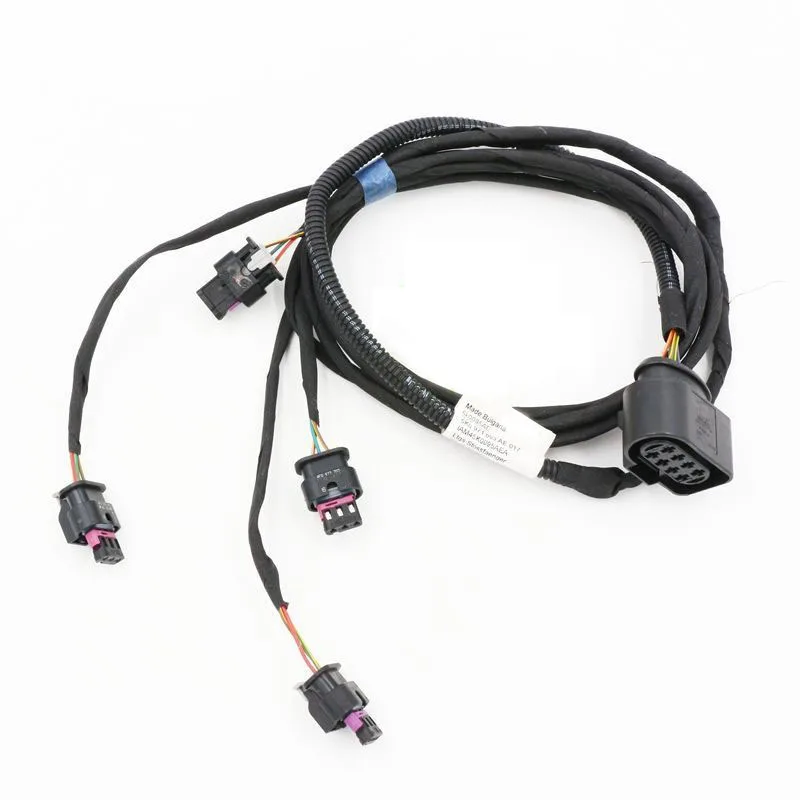
The 80B971111 harness serves Q5 models from the second-generation platform spanning three model years. This generation introduced updated steering rack designs with integrated torque sensors requiring revised harness pinouts compared to first-generation Q5 vehicles. The harness includes shielded twisted-pair wiring for sensor signals, reducing electromagnetic interference from nearby high-current systems like starter motors and alternators.
Second-generation Q5 steering systems employ redundant sensor circuits for safety-critical steering angle data. The harness therefore contains duplicate signal pathways with independent grounds, allowing the system to maintain partial functionality if one circuit fails. Wire gauge specifications use 0.75mm² for sensor power supplies and 1.5mm² for motor phase connections, meeting VW Group electrical system standards LV214 for automotive wiring.
Installation Best Practices
Proper installation begins with battery disconnection and waiting 15 minutes for capacitor discharge in the EPS control module. This prevents inadvertent airbag deployment during steering column work. Remove the lower dashboard trim panels to access the bulkhead connector, then release the steering column locking mechanisms to allow sufficient movement for harness routing. Use plastic trim tools rather than metal to avoid damaging connector housings.
Route the new harness through existing clips and grommets, maintaining factory-specified clearances from hot exhaust components and sharp chassis edges. Ensure connectors fully seat with audible clicks, verifying locking tabs engage completely. Torque specifications for rack-mounted connectors typically require 4-6 Nm applied to securing bolts, preventing vibration-induced loosening while avoiding thread stripping in aluminum housings.
Post-Installation Procedures
Recommended Products
Hand-picked accessories related to this article
SaleFor GOLF MK7 Power Steering Left Hand Drive Wiring Harness 5Q1971111AA 5Q1 971 111 AA 5Q1971111 AA
 Sale
Sale80B971111 For Q5 POWER STEERING GEAR RACK WIRE WIRING HARNESS CABLE 2018 - 2020 80B 971 111
 Sale
Sale2026 HOTNew Bolanston DQL-32 Steering Gear Wiring Harness For Audi Q5 8R 2008-2017 Electric Power Steering EPS Control Unit OE 8
After harness installation, perform steering angle sensor calibration using VCDS or VAS diagnostic equipment. This procedure centers the electronic reference point, preventing offset steering wheel position and ensuring ESC/ABS integration functions correctly. Drive the vehicle in a straight line on level ground during calibration, then execute full lock-to-lock turns to establish rack travel limits in the control module memory.
Quality Indicators and Common Issues
Genuine replacement harnesses feature embossed part numbers on connector housings and date codes molded into cable jackets. Wire insulation should be flexible PVC or cross-linked polyethylene, not stiff or brittle material indicating poor-quality compounds. Connector pins must show consistent plating without exposed copper, which oxidizes rapidly and increases contact resistance leading to intermittent faults.
Counterfeit harnesses often use undersized wire gauges that meet visual specifications but lack sufficient ampacity for motor current loads. Measure wire diameter with calipers if authenticity is questionable—genuine 1.5mm² wire measures approximately 1.4mm diameter including insulation. Terminal crimps should be hex-compressed with visible crimp indentations, not merely folded or pinched closed.
Key Takeaways
- Power steering harnesses are vehicle-specific; verify exact part numbers for your model year and steering system type
- Left-hand drive and right-hand drive configurations use different harness lengths and routing paths
- Proper installation requires steering angle sensor calibration with diagnostic equipment after harness replacement
- Quality harnesses feature shielded wiring, gold-plated signal pins, and IP67-rated connectors for moisture resistance
- Wire gauge specifications directly affect current-carrying capacity and long-term reliability under load conditions
Alternatives and Related Components
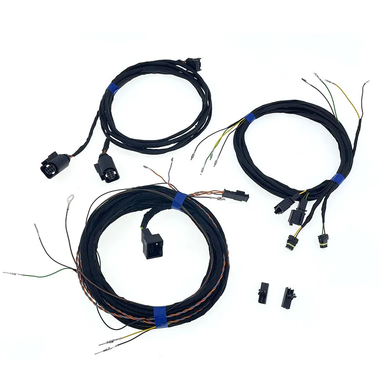
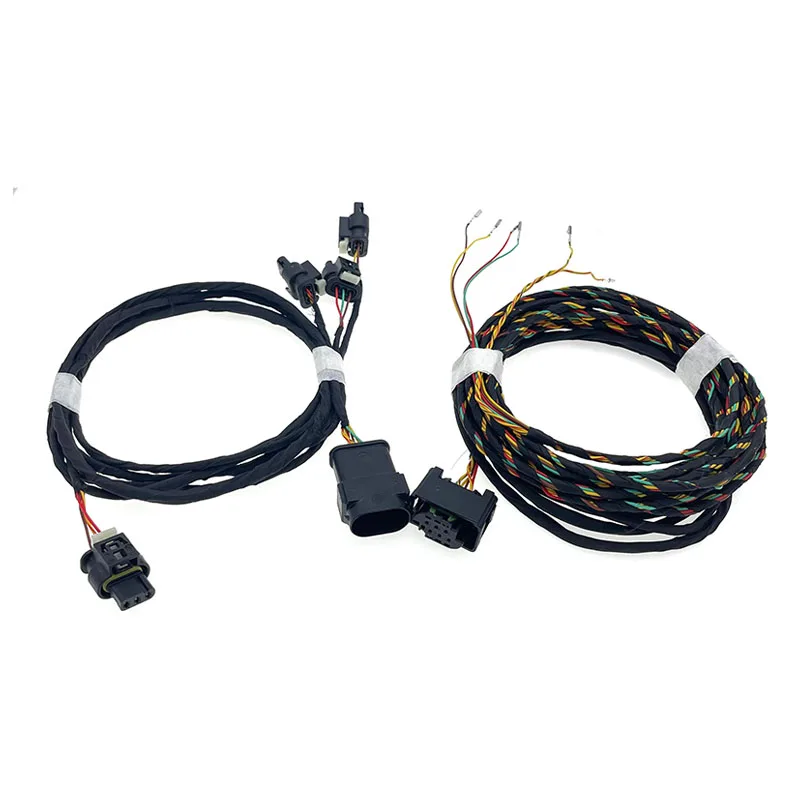
Beyond the featured harnesses, similar footwell lighting harnesses and interior wiring assemblies serve different electrical circuits but share common connector types. These auxiliary harnesses do not replace power steering components but may require simultaneous replacement during extensive electrical repairs. Air conditioning filter covers and interior trim pieces facilitate access during installation but are not functionally related to steering system operation.
Frequently Asked Questions
Can I repair a damaged power steering harness instead of replacing it?
Temporary repairs using solder and heat-shrink tubing may restore function, but harness replacement is recommended for long-term reliability. Steering systems are safety-critical components where electrical failures can cause sudden loss of power assist at highway speeds. Factory harnesses use specialized wire types and shielding configurations difficult to replicate with field repairs, making complete replacement the safer option.
How do I identify which harness my vehicle needs?
Remove the existing harness and locate the embossed part number on the largest connector housing, typically found at the bulkhead pass-through point. Cross-reference this number with your vehicle's VIN using ETKA parts diagrams or dealer parts systems. Left-hand drive and right-hand drive variants use different part numbers despite external similarity, so verify your vehicle's configuration before ordering.
What causes power steering harness failures?
Common failure modes include wire strand breakage from repeated flexing during steering inputs, insulation degradation from heat exposure near exhaust components, and corrosion of connector pins from moisture ingress through damaged seals. Rodent damage also affects harnesses routed through accessible underhood areas. Harnesses typically last the vehicle's lifetime but may fail prematurely in harsh environments or with aftermarket installations that alter routing paths.
Do these harnesses require programming after installation?
The harnesses themselves contain no electronic components requiring programming, but the steering system requires angle sensor calibration after installation. This procedure uses diagnostic software to establish the electronic center point and rack travel limits, ensuring proper ESC and lane-keeping system operation. Most independent repair shops can perform this calibration with VCDS or equivalent diagnostic tools in approximately 10 minutes.
This article was produced through comprehensive AI-powered research and editorial tools. While we strive for accuracy, all vehicle modifications, product purchases, and installation decisions are undertaken entirely at your own risk and responsibility. We recommend consulting a qualified automotive professional before making any changes to your vehicle.