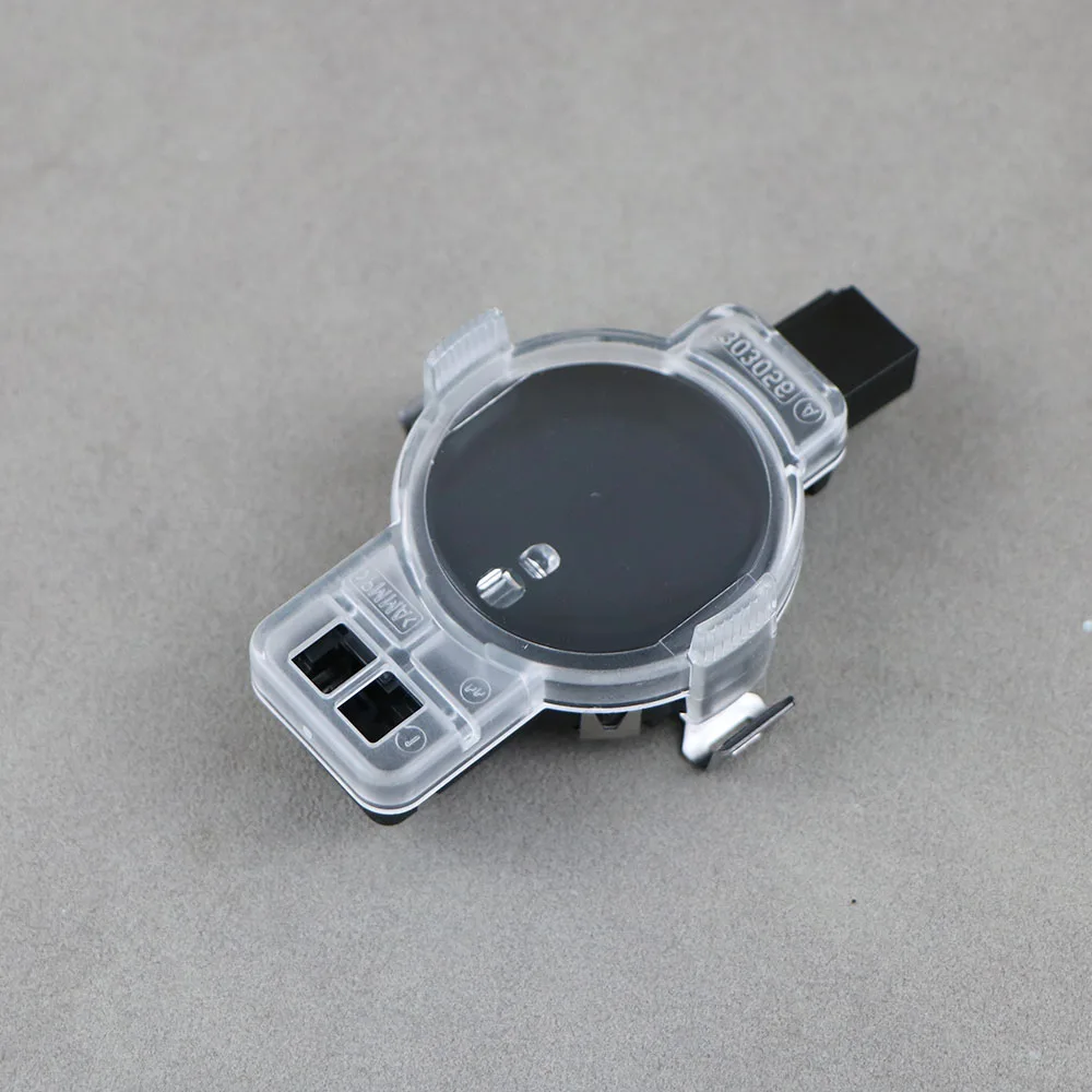
The 8W8 827 566 E rear view camera for Audi A5 B9 represents an OEM-compatible retrofit solution that integrates dynamic highline guidance lines into vehicles originally equipped without factory cameras. This review examines the technical specifications, installation requirements, and coding procedures necessary for proper integration with the MMI system.
Compatibility and Part Numbers
The 8W8 827 566 E camera maintains cross-compatibility across multiple VAG platform vehicles. The same camera works on Audi A4 B9, A5 F5, and A6 C8 models. Body-specific part variations include 3V0 827 566 L for Sedan configurations and 3V0 827 566 M for Avant wagons, though the core 8W8 827 566 E part number remains the standard highline specification.
Facelift A5 B9 models with MIB3 MMI units require additional consideration. These later production vehicles use a different video signal cable architecture and may need a dedicated adapter for proper signal conversion. Pre-facelift models with MIB2 systems typically integrate without additional adapters when using the correct wiring harness.
CAN Bus Wiring Specifications
The camera operates through CAN bus communication rather than simple analog video input. Two specific CAN signal wires handle the data transmission: Orange+Purple connects to PIN 30 for CAN HIGH, while Orange+Brown connects to PIN 12 for CAN LOW. This differential signaling method ensures reliable communication with the gateway module even in electrically noisy environments.
Beyond CAN communication, four additional wires complete the connection. Two video signal wires (Black and Transparent) carry the composite video feed to the MMI display unit. Power delivery uses standard automotive conventions with White providing +12V switched power and Brown serving as ground reference. The switched power typically derives from the reverse lamp circuit for automatic activation.
VCDS Coding Requirements
Successful installation of the 8W8 827 566 E camera with wiring harness demands three specific coding operations through VCDS or equivalent diagnostic software. First, the 6C module must be registered in the central gateway to establish proper CAN bus communication pathways. The camera arrives pre-parameterized with 6C long code, but gateway registration remains essential for module recognition.
Second, if the vehicle includes factory parking assistance sensors, the Body Control Module (BCM) in address 09 requires activation coding to enable camera functionality. Vehicles equipped with rear sensors only need the specific code 0237060102002001000040 for proper integration. This byte string defines sensor quantity, arrangement, and camera coordination parameters.
Third, Module 5F requires enabling the BAP_Gen2_VPS function. This adaptation activates the visual parking system within the MMI software structure, allowing the display to properly interpret and render camera feed with dynamic guidance overlays. Without this activation, the camera may transmit video but fail to display correctly.
Installation Procedure
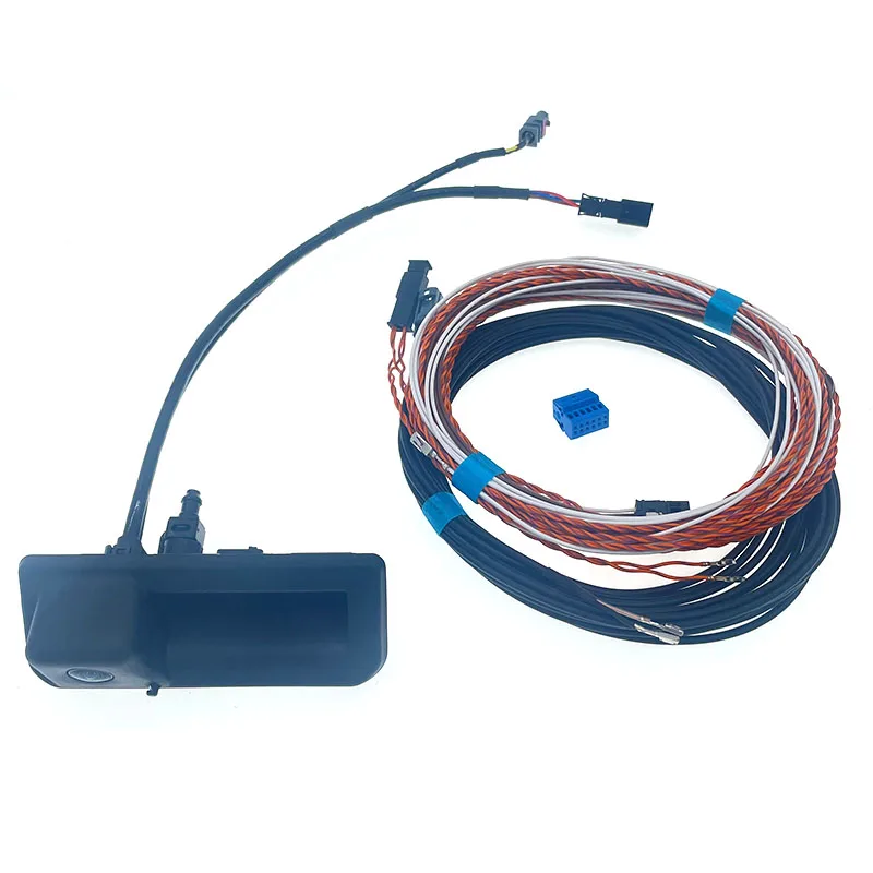
Physical installation begins with trunk liner removal to access the license plate housing area. The camera mounts in the designated position on the trunk handle or tailgate, depending on body style. Routing the harness through existing grommets prevents water ingress and maintains factory appearance. The video signal wires run forward to the MMI unit location, typically behind the dashboard center stack.
CAN bus wire termination requires careful attention to polarity and pin assignments. Incorrect CAN HIGH/LOW connections represent the most common installation error. Using a multimeter to verify pin identification before making connections prevents potential communication failures. The video signal wires connect directly to the MMI unit's camera input connector, which may be present but unused on non-camera equipped vehicles.
Troubleshooting Common Issues
When the camera fails to display after installation, three primary failure points warrant investigation. First, verify CAN bus wire connections match the specified pin assignments. Reversed CAN HIGH/LOW connections prevent module communication entirely. Second, confirm gateway module registration completed successfully through VCDS module scanning. An unregistered 6C module cannot communicate even with correct wiring.
Third, check that video signal wires maintain continuity from camera to MMI unit. Break or poor contact in these wires results in no image display despite proper CAN communication. For MIB3 equipped vehicles showing distorted or absent video, verify the correct adapter installation for video signal format conversion.
Recommended Products
Hand-picked accessories related to this article
Highline Guidance Line Features
The highline designation indicates dynamic guidance line capability rather than static overlay graphics. The system calculates projected vehicle path based on steering wheel angle input and adjusts the displayed guidelines accordingly. This functionality provides accurate backing trajectory visualization during parking maneuvers, particularly valuable in tight spaces where precise positioning matters.
The dynamic lines update in real-time as steering input changes, showing exactly where the vehicle will travel at current steering angle. This surpasses basic static line systems that only show vehicle width without accounting for steering position. Full integration requires proper steering angle sensor coding within the adaptation channels.
OEM vs Aftermarket Considerations
The 8W8 827 566 E carries OEM part number structure and specification compliance, distinguishing it from generic universal backup cameras. OEM-compatible construction ensures proper fit within the license plate housing without modification or visible gaps. The connector architecture matches factory specifications, allowing direct harness integration without splicing or adapters beyond the MIB3 video converter where necessary.
Image quality from OEM-specification cameras typically exceeds aftermarket alternatives through superior sensor selection and lens optics. The camera provides adequate low-light performance for evening parking situations. Resolution meets MMI display capabilities without overshooting into wasted bandwidth or undershooting into pixelated imagery.
Key Takeaways
- CAN bus wiring requires Orange+Purple to PIN 30 (CAN HIGH) and Orange+Brown to PIN 12 (CAN LOW) for proper communication
- VCDS coding demands three operations: gateway 6C registration, BCM camera activation, and Module 5F BAP_Gen2_VPS enabling
- MIB3 facelift models need additional video signal adapter for compatibility
- Code 0237060102002001000040 specifically applies to vehicles with rear sensors only
- Highline specification provides dynamic steering-responsive guidance lines rather than static overlays
Frequently Asked Questions
Does the 8W8 827 566 E camera work on pre-facelift A5 B9 models?
Yes, the camera fully supports pre-facelift A5 B9 vehicles with MIB2 MMI systems using the standard wiring harness without additional adapters. Facelift models with MIB3 require a video signal adapter for proper integration.
Can I install this camera without VCDS coding software?
No, proper camera function requires VCDS or equivalent diagnostic software to register the 6C module in the gateway, activate the camera in BCM address 09, and enable the BAP_Gen2_VPS function in Module 5F. The camera will not display without these coding operations.
What causes the camera to show no image after installation?
The three most common causes are reversed CAN bus wire connections (CAN HIGH/LOW swapped), incomplete gateway module registration through VCDS, or broken continuity in the video signal wires between camera and MMI unit. Verify all three before investigating other potential issues.
Do the dynamic guidance lines work immediately after installation?
Dynamic guidance lines require proper steering angle sensor coding in addition to standard camera coding. If lines appear static rather than adjusting with steering input, verify steering angle sensor adaptation channels are correctly configured within Module 5F settings.
This article was produced through comprehensive AI-powered research and editorial tools. While we strive for accuracy, all vehicle modifications, product purchases, and installation decisions are undertaken entirely at your own risk and responsibility. We recommend consulting a qualified automotive professional before making any changes to your vehicle.